System Notes
We have published details of the algorithms and approaches we use. See the following publications:
Crest: Novel Ocean Rendering Techniques in an Open Source Framework, Advances in Real-Time Rendering in Games, ACM SIGGRAPH 2017 courses https://advances.realtimerendering.com/s2017/index.html
Multi-resolution Ocean Rendering in Crest Ocean System, Advances in Real-Time Rendering in Games, ACM SIGGRAPH 2019 courses http://advances.realtimerendering.com/s2019/index.htm
Core Data Structure
The backbone of Crest is an efficient Level Of Detail (LOD) representation for data that drives the rendering, such as surface shape/displacements, foam values, shadowing data, water depth, and others. This data is stored in a multi-resolution format, namely cascaded textures that are centered at the viewer. This data is generated and then sampled when the water surface geometry is rendered. This is all done on the GPU using a command buffer constructed each frame by BuildCommandBuffer.
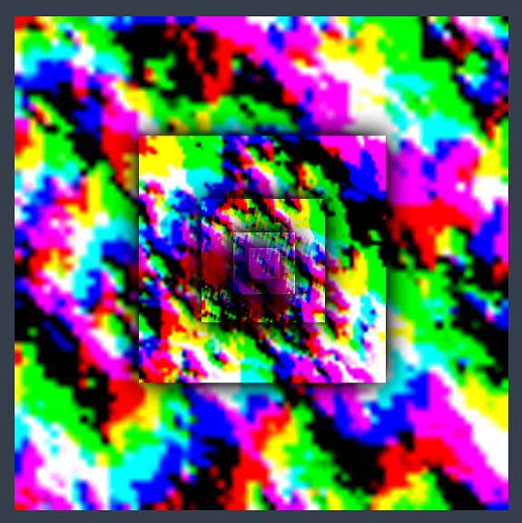
Let’s study one of the LOD data types in more detail. The surface shape is generated by the Animated Waves LOD Data, which maintains a set of displacement textures which describe the surface shape. A top down view of these textures laid out in the world looks as follows:

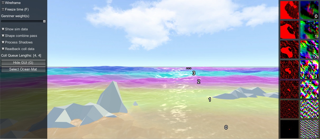
Each LOD is the same resolution (256x256 here), configured on the Water Renderer script. In this example the largest LOD covers a large area (4km squared), and the most detail LOD provides plenty of resolution close to the viewer. These textures are visualised in the Debug GUI on the right hand side of the screen:

In the above screenshot the foam data is also visualised (red textures), and the scale of each LOD is clearly visible by looking at the data contained within. In the rendering each LOD is given a false colour which shows how the LODs are arranged around the viewer and how they are scaled. Notice also the smooth blend between LODs - LOD data is always interpolated using this blend factor so that there are never pops are hard edges between different resolutions.
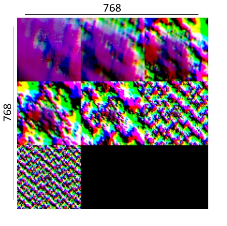
In this example the LODs cover a large area in the world with a very modest amount of data. To put this in perspective, the entire LOD chain in this case could be packed into a small texel area:

A final feature of the LOD system is that the LODs change scale with the viewpoint. From an elevated perspective, horizontal range is more important than fine wave details, and the opposite is true when near the surface. The Water Renderer has min and max scale settings to set limits on this dynamic range.
When rendering the water, the various LOD data is sampled for each vertex and the vertex is displaced. This means that the data is carried with the waves away from its rest position. For some data like foam this is fine and desirable. For other data such as the depth to the water floor, this is not a quantity that should move around with the waves and this can currently cause issues, such as shallow water appearing to move with the waves as in #96.
Implementation Notes
On startup, the Water Renderer script initialises the water system and asks the WaterBuilder script to build the water surface. As can be seen by inspecting the water at run-time, the surface is composed of concentric rings of geometry tiles. Each ring is given a different power of 2 scale.
At run-time, the water system updates its state in LateUpdate, after game state update and animation, etc. Water Renderer updates before other scripts and first calculates a position and scale for the water. The water GameObject is placed at sea level under the viewer. A horizontal scale is computed for the water based on the viewer height, as well as a _viewerAltitudeLevelAlpha that captures where the camera is between the current scale and the next scale (\(\times2\)), and allows a smooth transition between scales to be achieved.
Next any active water data are updated, such as animated waves, simulated foam, simulated waves, etc. The data can be visualised on screen if the Debug GUI script from the example content is present in the scene, and if the Show shape data on screen toggle is enabled. As one of the water data types, the water shape is generated using an FFT and copied into the animated waves data. Each wave component is rendered into the shape LOD that is appropriate for the wavelength, to prevent over- or under- sampling and maximize efficiency. A final pass combines the shape results from the different FFT components together. Disable the Shape combine pass option on the Debug GUI to see the shape contents before this pass.
Finally BuildCommandBuffer constructs a command buffer to execute the water update on the GPU early in the frame before the graphics queue starts. See the BuildCommandBuffer code for the update scheduling and logic.
The water geometry is rendered by Unity as part of the graphics queue, and uses the Crest/Water shader. The vertex shader snaps the verts to grid positions to make them stable. It then computes a lodAlpha which starts at 0 for the inside of the LOD and becomes 1 at the outer edge. It is computed from taxicab distance as noted in the course. This value is used to drive the vertex layout transition, to enable a seamless match between the two. The vertex shader then samples any required water data for the current and next LOD scales and uses lodAlpha to interpolate them for a smooth transition across displacement textures. Finally, it passes the LOD geometry scale and lodAlpha to the water fragment shader.
The fragment shader samples normal and foam maps at 2 different scales, both proportional to the current and next LOD scales, and then interpolates the result using lodAlpha for a smooth transition. It combines the normal map with surface normals computed directly from the displacement texture.